IoT Actuator Hello World
What you will learn in this tutorial:
- Hardware setup to remotely control the LED
- Message Setup
- Iottly Code
Preconditions
After connecting your Raspberry Pi:
you can follow this tutorial.
Hardware setup
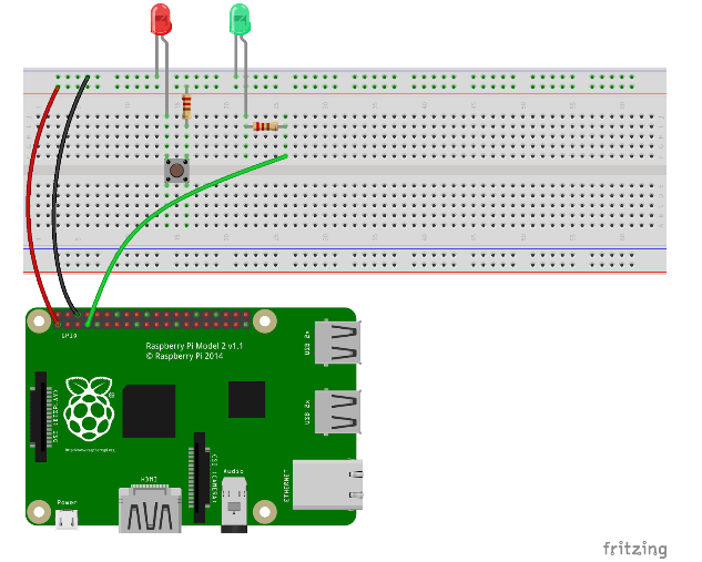
In this exercise we are going to use pin #7 as an output (actuator) to control the green LED
- Create a circuit like the one in the sketch
- This time the green wire connect the LED anode to RPi Pin #7 (through a 220Ohm resistor)
Raspberry Pi 1 Rev 1 Pinout reference here
Raspberry Pi 1 Rev 2 Pinout reference here
Raspberry Pi 2/3 Pinout reference here
Raspberry Pi zero w Pinout reference here
Let’s use Iottly to configure a command to remotely control the LED
Message Setup
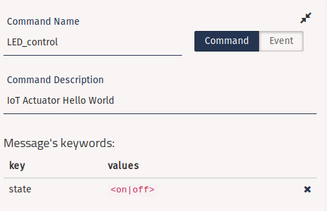
Create the following message:
- Name:
- LED_control
- Description:
- IoT Actuator Hello World
- Keywords:
- key: “state”
- Type: Multiple Value
- Values:
- on
- off
- key: “state”
Iottly Code
Edit the following snippets in the “Management Scripts” panel:
init:- Initialize Pin #7 to be managed as output
def init():
  #...

  #-----------------------------------------------------------------------------#

  # here your code!!

  pin = "7"
  GPIO.setup(int(pin), GPIO.OUT)

  #-----------------------------------------------------------------------------#
LED_control:- Keep in mind the format of the incoming message:
{"LED_control":{"state":"<on|off>"}} - Set the state of Pin #7 to
TrueorFalse, based on the value of the'state'keyword in the message
- Keep in mind the format of the incoming message:
def LED_control(command):
  #...
  cmdpars = command["LED_control"]
  #...
  #-----------------------------------------------------------------------------#

  # here your code!!
  state = {
    'on': True,
    'off': False
  }.get(cmdpars['state'], False)
  GPIO.output(7,state)
  #-----------------------------------------------------------------------------#
-
-
Test the “IoT Actuator Hello World” from the Console panel